
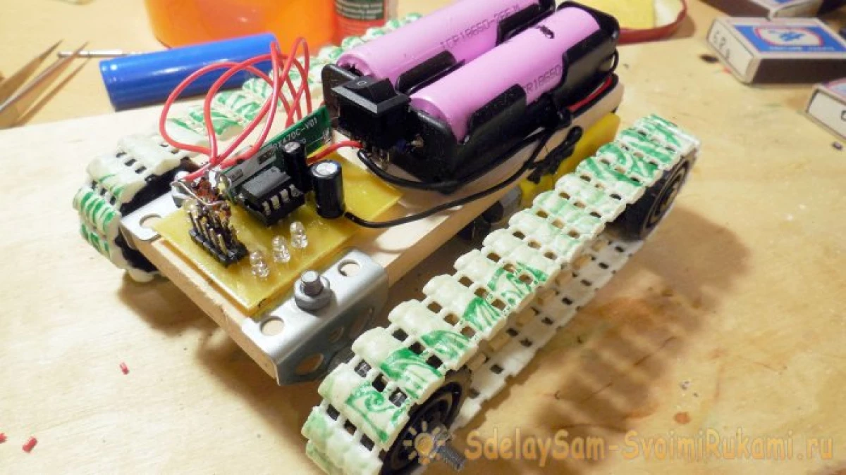
Consider the creation of a typewriter on a caterpillar with a fairly elementary design, to assemble which you can literally for a couple of evenings. The whole design can be divided into two parts - a tracked chassis and an electrical part that will provide remote control of the machine from the remote control.
Manufacturing chassis
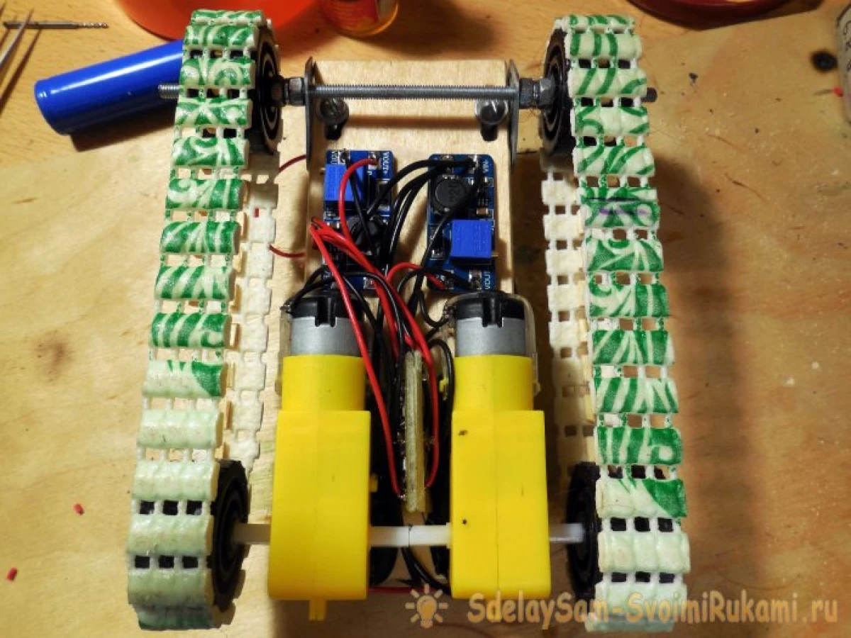
It takes not so many materials: Caterpillar will be driven by a pair of gearboxes, the basis of the entire design will be a small piece of thick plywood, you will also need several plastic wheels for which the caterpillars will rotate. For a machine, you can use almost any suitable gearboxes, ideal "yellow", which can be found in many stores of radio components, or buy on Ali, the gearbox gives a gear ratio 1:48, which for this case is the most optimal value. .
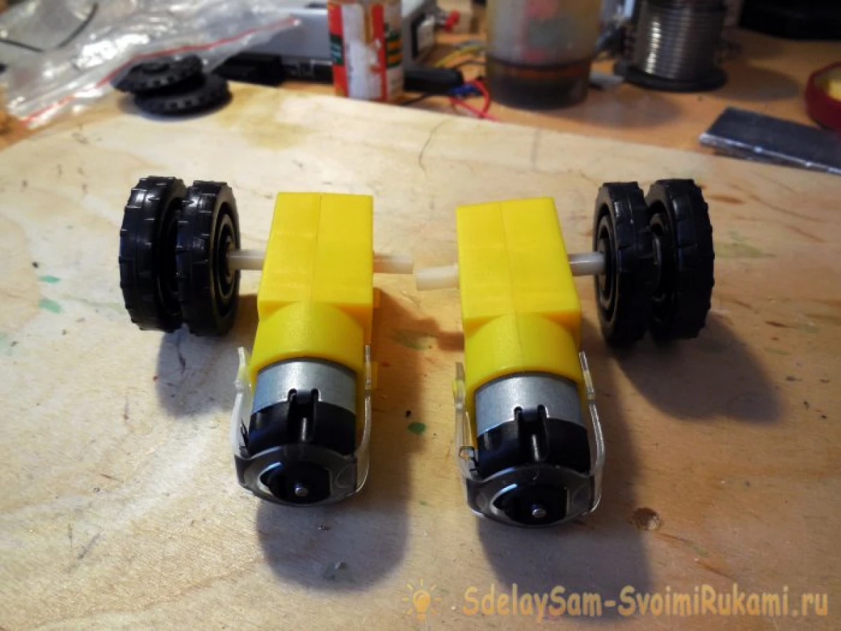
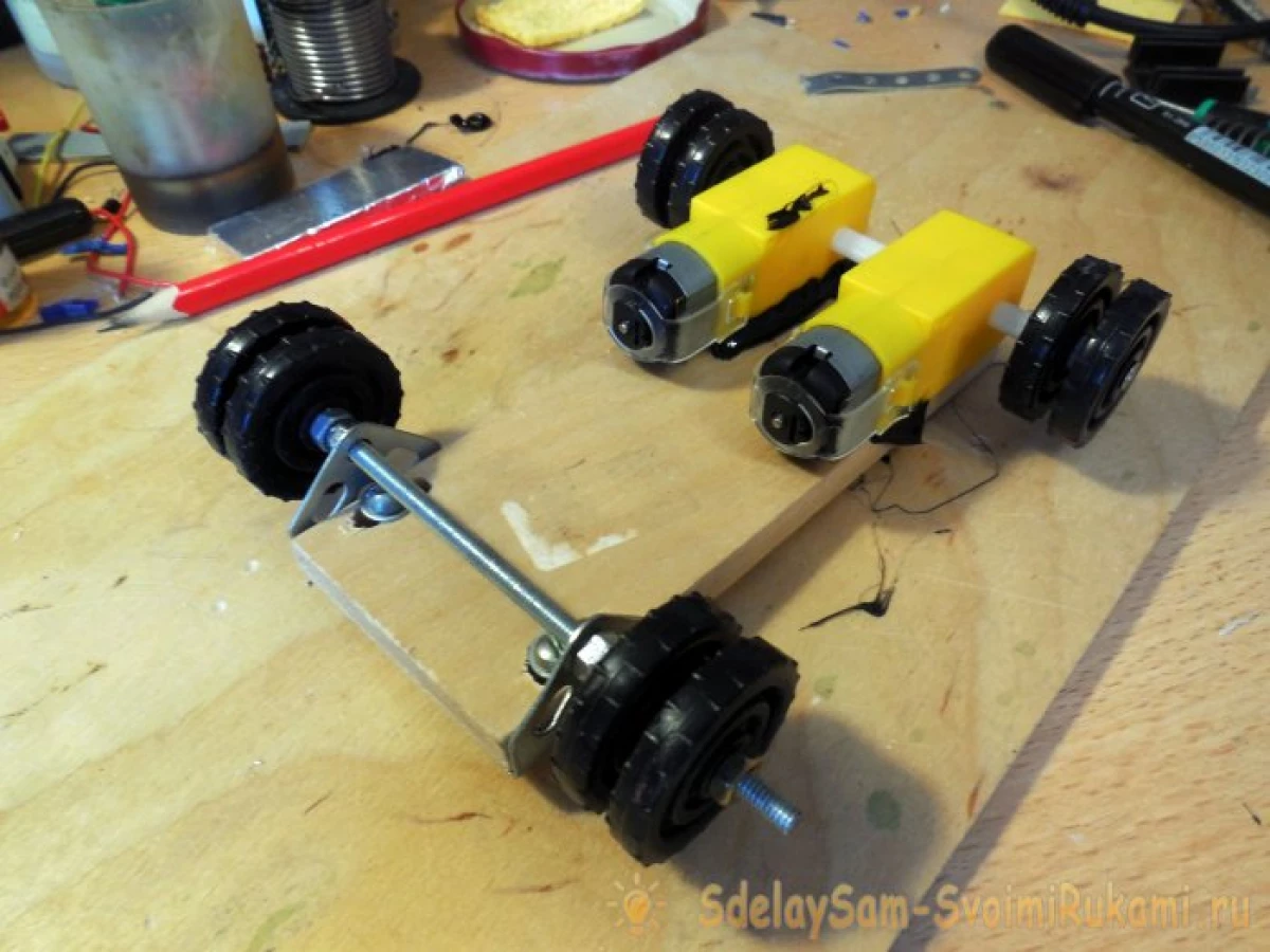
Each gearbox has access to two shafts, only one shaft will be activated for a caterpillar chassis, only one shaft will be involved, the second can be removed at all or leave if these motors are still needed in other projects. It is necessary to fasten the wheels on the shafts - to make it faster, screwing up the screw itself into the tree itself (inside it is hollow), therefore, the wheels will sleep well. For additional fixation, and in order not to unwind the screws, you can abundantly lubricate the connection with glue. Please note that the wheel is double - there is a gap between each of the wheels about 3-4 mm, the caterpillar will be fixed with it.
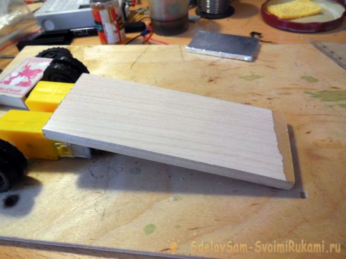
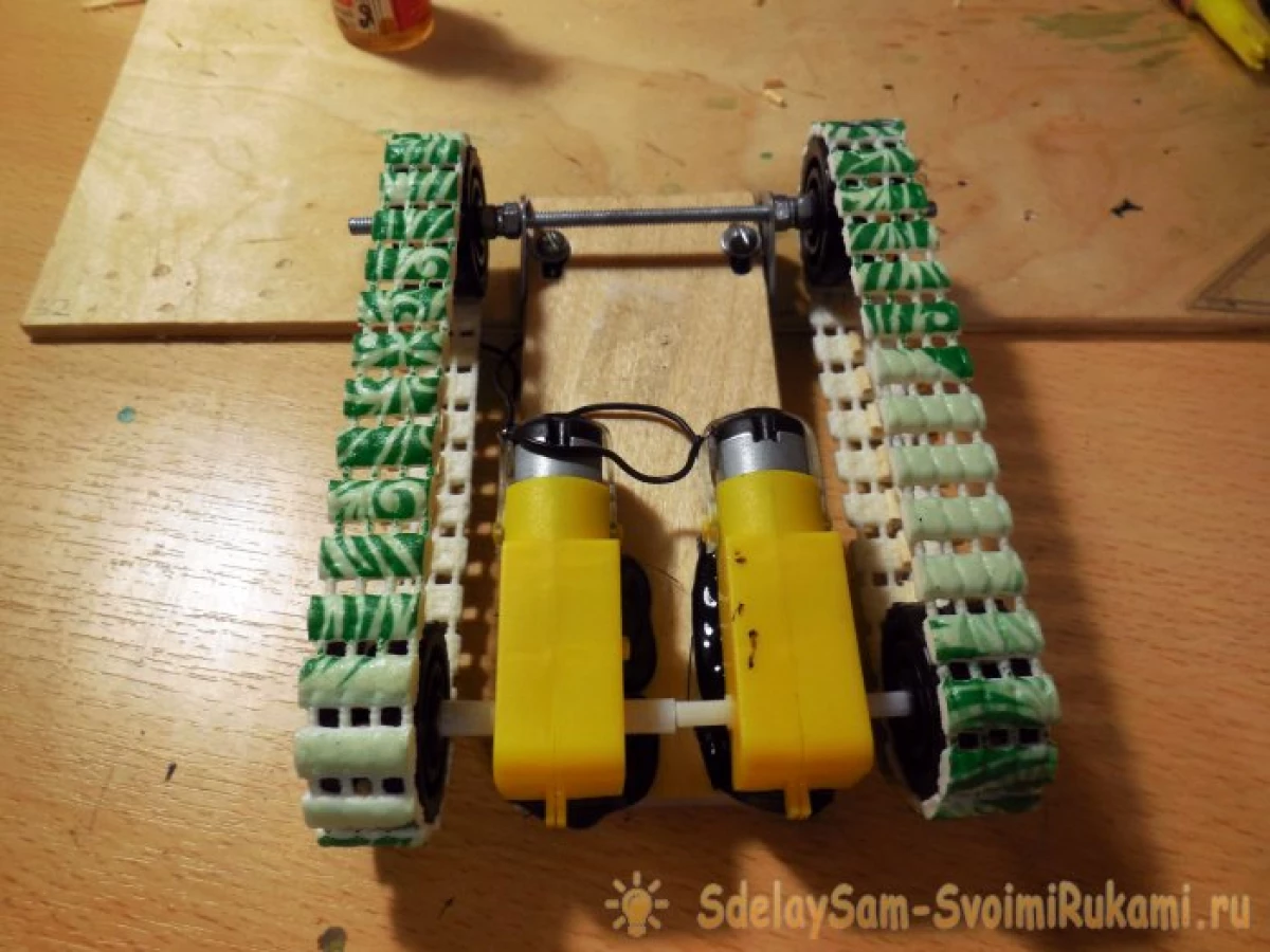
Motors are fixed on a piece of durable plywood, its size can be selected arbitrarily, depending on the desired sizes of the machine. No convenient places for fastening these gear motors are not provided, so I recorded them using thermoclause - good adhesive rods provide excellent quality compound, as experience showed.
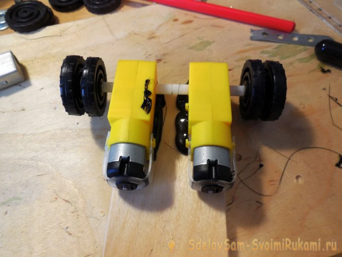
Next, in the opposite side of the motor, it is necessary to secure the corners for the axis of the front wheels. To do this, I highly recommend using the details from the children's iron designer - there you can find ready-made corners with holes. When drilling a hole in the plywood, it is necessary to take into account that in the future it will take the adjustment of the caterpillage tension, so it is necessary to drill a row of holes with a length of about 1-1.5 cm, which then combine into one oblong slot. Thus, the entire front axle will move backwards, fixing the bolts in the desired position.
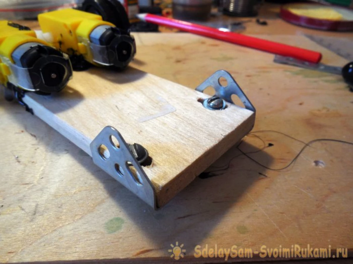
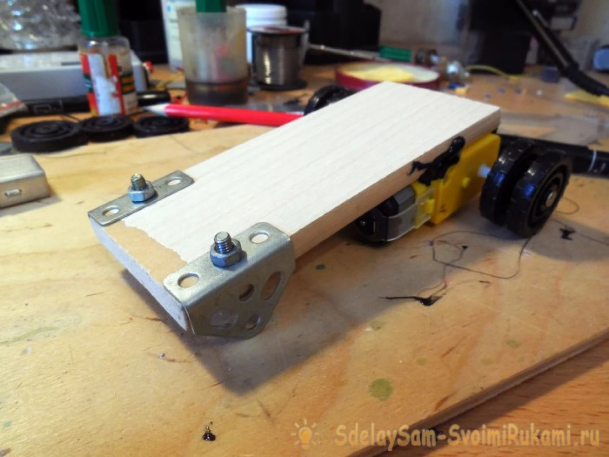
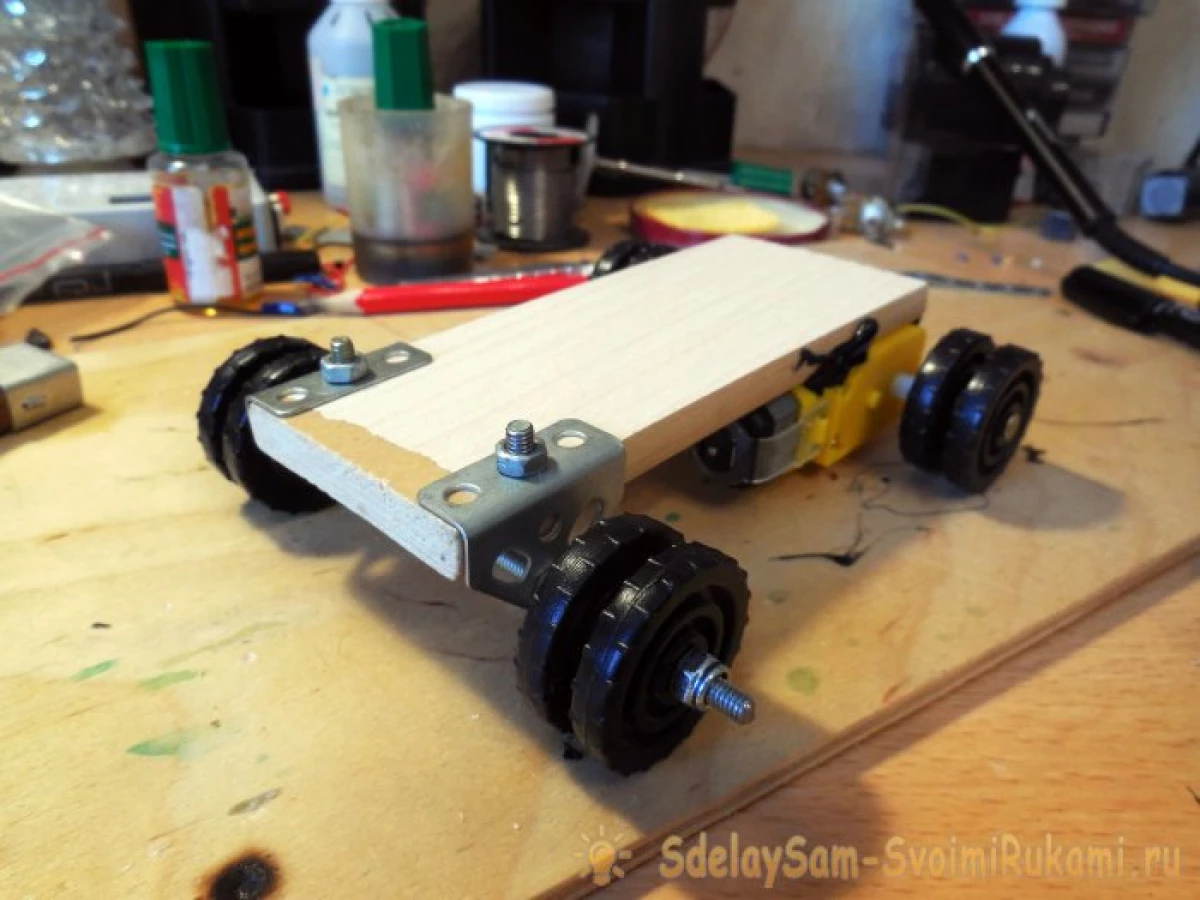
The hole in the holes in the corners, it is convenient to use M4, it gives sufficient hardness and is suitable for holes in the parts of the iron designer. The heel must be hard to fasten on the corners, it is convenient to use nuts with fixation for this nuts, they do not spin themselves when the machine will start ride. On the sides, the same double wheels are installed as behind, with the exact same gap. The wheels should freely rotate on the axis, it is possible to provide it by the same nuts with fixation. Please note that the left and right wheels must rotate independently of each other. Such wheels I took in the same iron designer, but you can cut similar to both plastic, or from dense cardboard, if you fold it in several layers and glue.
Manufacturing of caterpillars
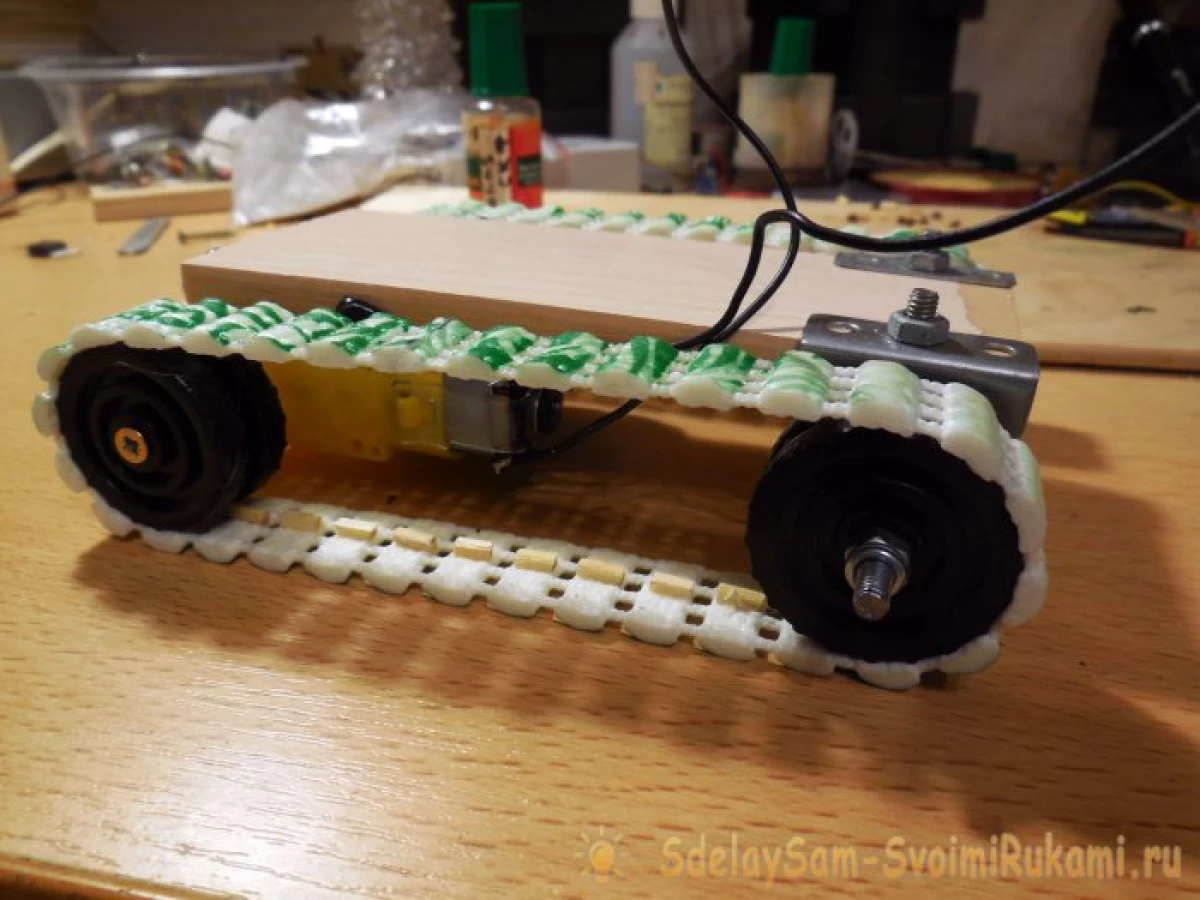
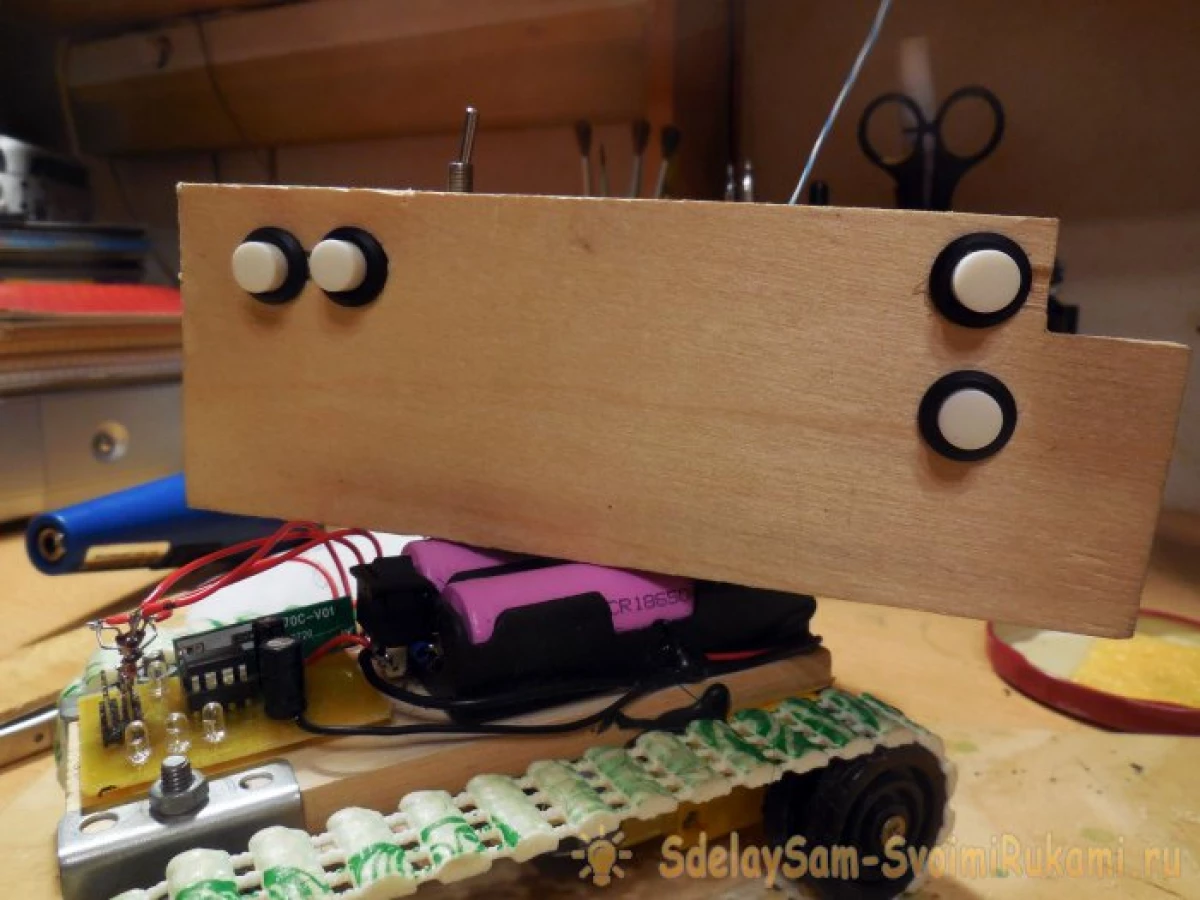
It is difficult to imagine, however, excellent caterpillars with good clutch are obtained from PVC bath rug, you can find it in almost any shop of household goods. Such a rug consists of a variety of flexible "strips", which are interconnected by parallel threads, what is needed to create a caterpillar. The ribbon is cut off the ribbon with a width of 1.5-2 cm, it should be equal to the width of the wheels used.
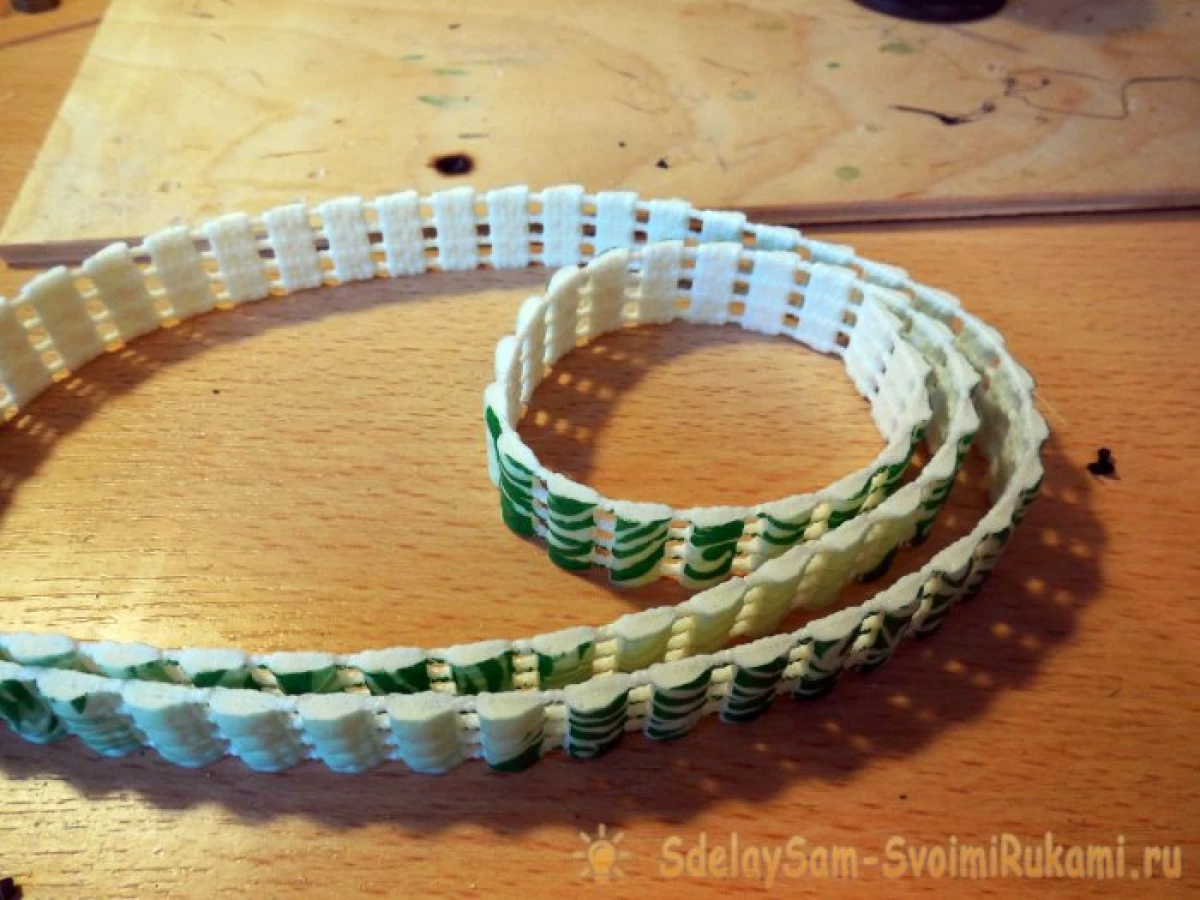
Then it is necessary to attach a tape to the wheels attached on the chassis and cut it down at the required length, then the ends of the ribbon are glued with superclaim. After the glue dries, you can try the caterpillar on the chassis and even turn on the motor - the caterpillar will rotate, but it will quickly fall from the wheels.
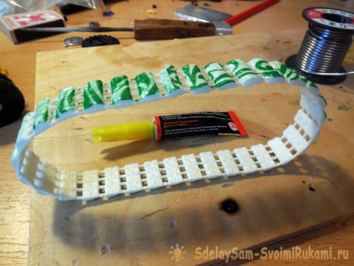
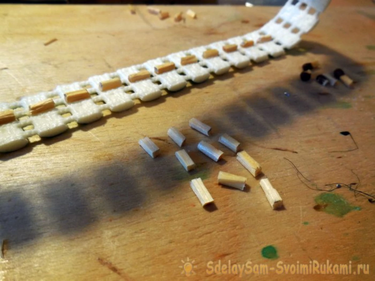
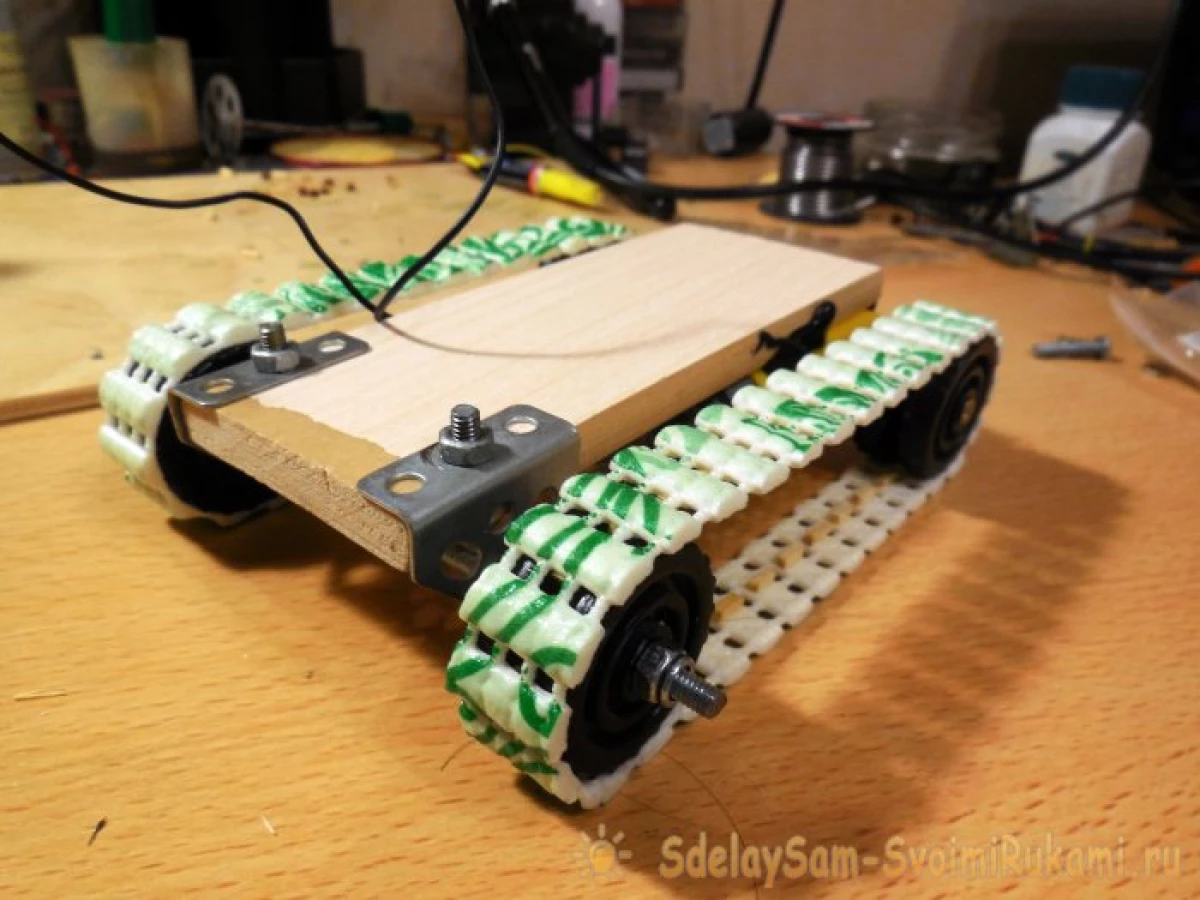
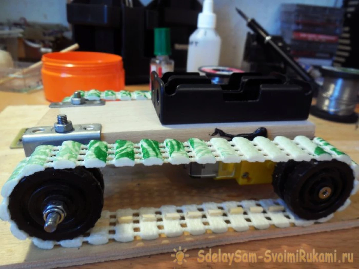
In order for the caterpillar to do not fall from the wheels, even when the future machine will move obstacles, you need to make convex stops in the center of the caterpillar. When rotating, they will fall into the gap between the wheels, without giving the caterpillar to get away. You can make such stops in many ways, I decided to stick the matches for each "step" of the caterpillars, as the experience showed, this method turned out to be a worker and with sufficient tension of the caterpillar did not fit at all. The matches are cut into segments of a length of 5-6 mm and glued, as shown in the photo below, all the same superchalters are used - it ensures good strength of the connection with the PVC mat material.
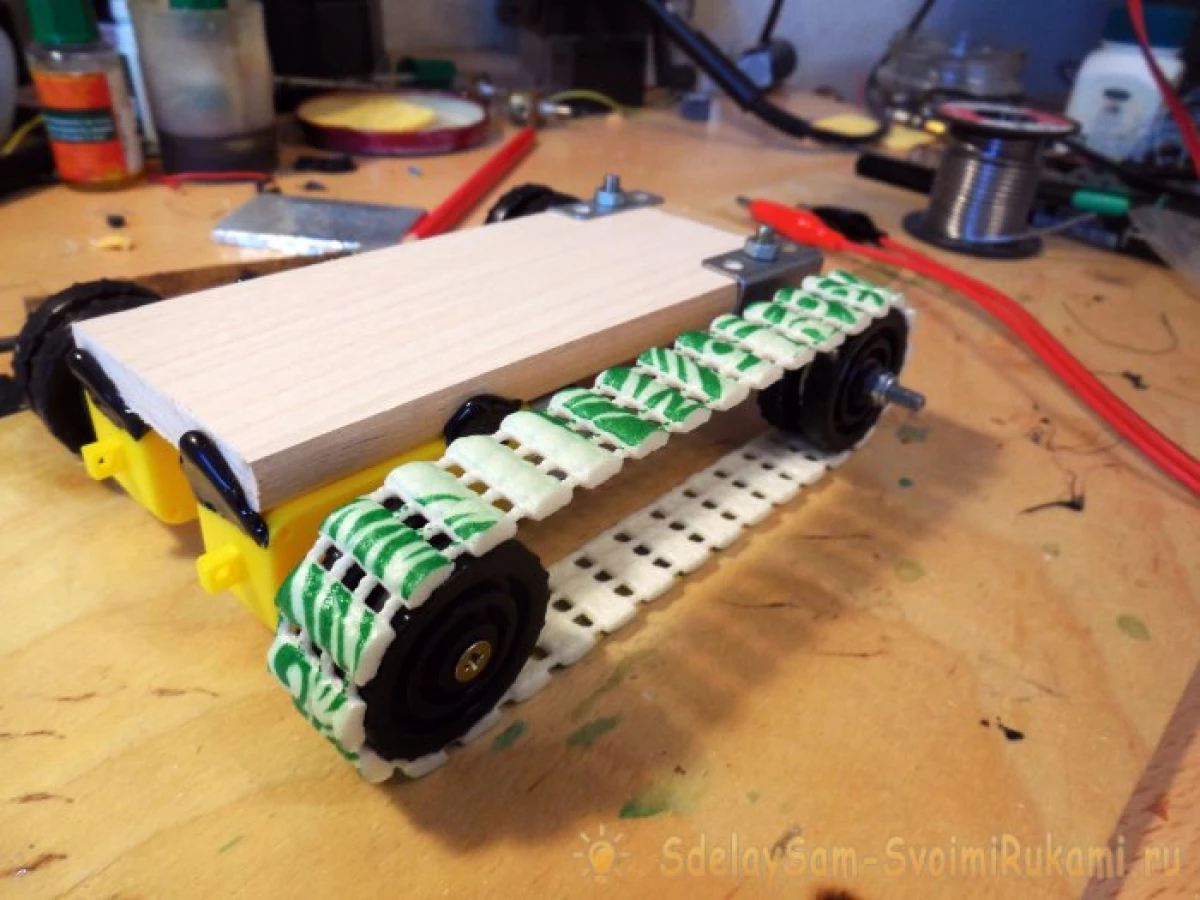
All the same actions need to be done with a second caterpillar. After sticking the caterpillars, you can read ready - now they hope on the chassis and can already check how the future machine will go, feeding the battery voltage directly to both motor. If necessary, it is necessary to adjust the tension force - too weak the caterpillar will turn it out or subsidize, and too much stretched will rotate tightly, having an additional load on the motor.
Electrical part
In the electrical part, several boards will be needed: the receiver and transmitter cards for transmitting commands from the remote control, which increase the converters to power the motors, as well as the "Bridges" boards for the possibility of rotating each of the motors in both directions. The general scheme is such - the transmitter board will be installed in the console, the receiver board on the machine chassis. The increases converters convert voltage from batteries (3.7 - 4.2 volts) to 7-8 volts, from which the motors will already eat. If the motors develop sufficient speed and directly from the battery, then the transducers can not be installed. Driving motor rotation will be bridge circuits - special schemes with field transistors that can supply voltage or one polarity to output, or the other, depending on which input (in 1 or in 2) will receive a control signal from the receiver board. At first, we consider the schemes of the transmitter and the receiver, they are respectively represented below.
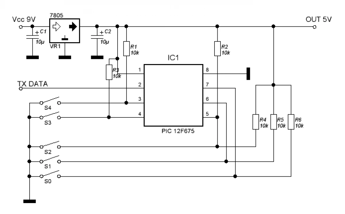
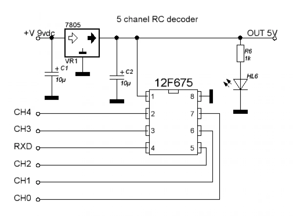
To be accurate, these circuits are called the encoder and decoder, and the receiver and transmitters and the transmitter are the ready-made RX-TX modules per frequency of 433 MHz, which can be easily bought on Ali or many stores of radio components -
Each of the modules has three contacts for connecting - plus power, minus, as well as the DATA contact for transmission or dataset. The above simple schemes provide a data transfer protocol, allowing you to process pressing 5 buttons. To control the typewriter, you will need only 4 channels (forward, back, right, left), so the 5th channel remains free and can be used under any goals, for example, turning on-off headlights. TXD and RXD contacts in circuits are connected accordingly to DATA contacts of the transmitter and receiver, in the rest of the scheme, simple and hardly require explanations. The supply voltage of the schemes themselves is 3.5-5 volts, however, if you set 78L05 stabilizers (they are listed on the diagrams), then you can feed from voltage 7 or more volt. Printing boards provide both options, you only need to install jumpers in the right places. For use in the machine, power and receiver, and the transmitter can be carried out directly from batteries without stabilizers. In each of the schemes there is a microcontroller - it must be flashing it with the corresponding firmware, the firmware is in the archive along with the files of the boards.
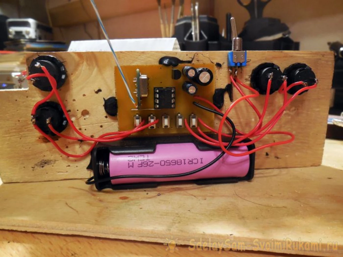
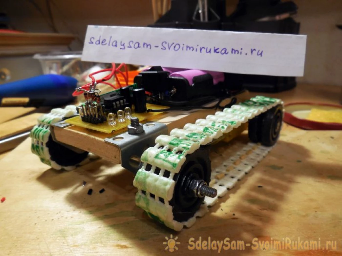
Manufacture of console
As one of the options, you can use the finished remote from some broken / unnecessary radio-controlled toy if there is enough space inside it to install the encoder board. Or you can make your own remote, as I did. As the basis, another truncation of plywood applied, mounted on it Holder for battery 18650, the coder fee with a receiver module, as well as 4 buttons, placing them to maximize control. Please note that the coder board already contains the boarding places for the board - their installation is optional, except for testing performance after assembly. The operating buttons are displayed from the boards on the wires, as in the photos below.
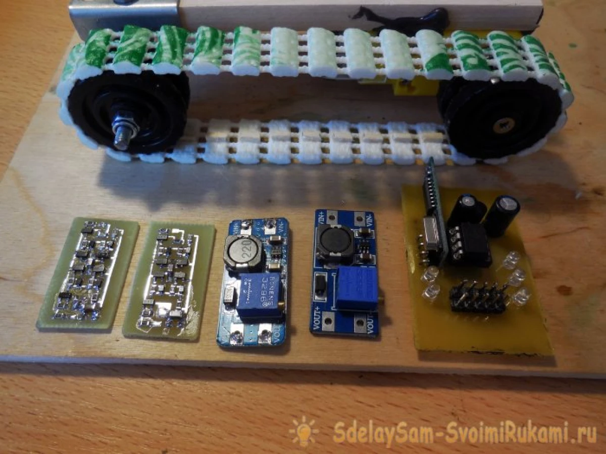
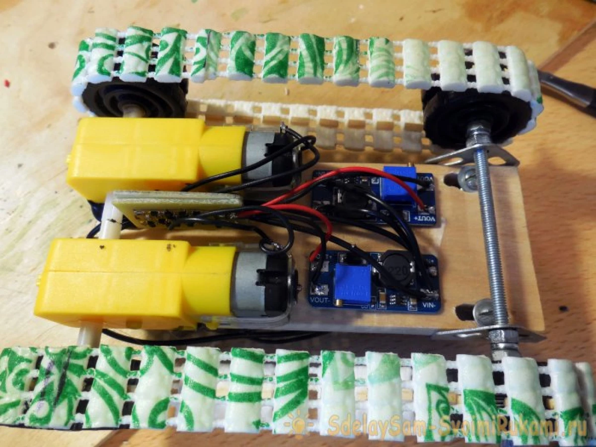
Installation of electronics on the chassis
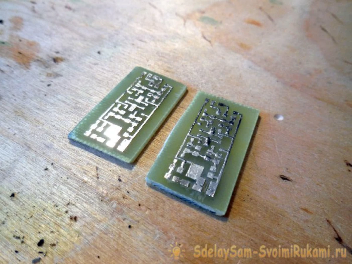
On the chassis itself, thus, besides the decoder board with a receiver module, two "Bridges" boards will be installed, and two converters. The use of two converters, one by one for each motor, is good because it will be possible to adjust the speed of each caterpillar. Motor gear, though the same, but still have some variation of parameters, therefore, even with the same feed voltage, it can give a slightly different revolutions, adjusting the voltage at the converter output can be achieved completely the same speed. Skotsky in speeds, even small, will lead to the fact that the machine will not go strictly forward, but with a small turn. You can see all the boards required for installation on the chassis below.
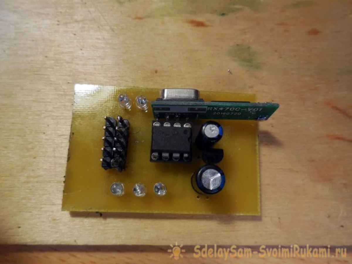
Detailed photo of the decoder board. Please note that it, just like the coder board, has several additional power capacitors - they will definitely not be superfluous in devices with microcontrollers.
Build a bridge scheme
It would seem - for which some kind of bridge is needed, because it is enough only with the help of the key to supply voltage on the motors. And she really is not needed if the typewriter is not required reverse - and the practice shows that it is completely uninteresting without it. Thus, it is necessary to assemble a small additional scheme, which will provide a polarity change for the motor. Polarism changes - the direction of movement changes.
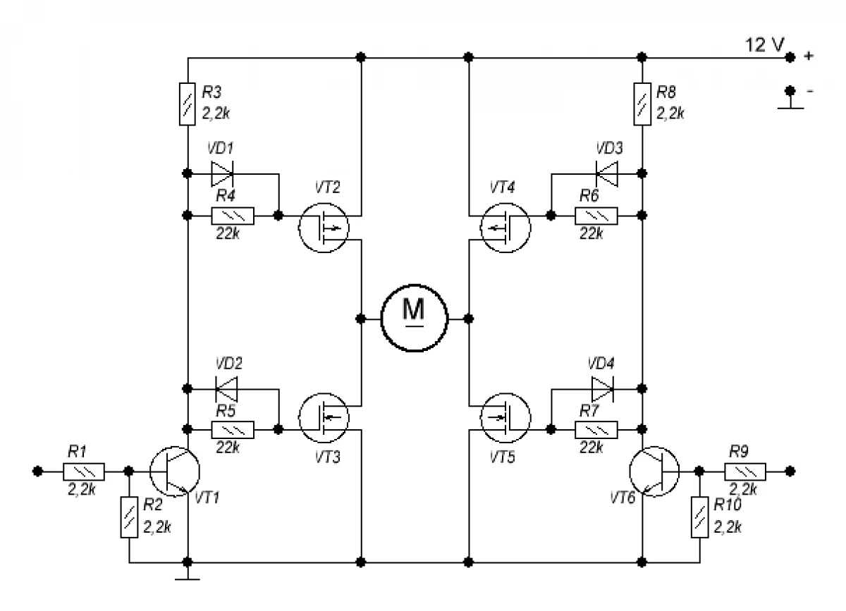
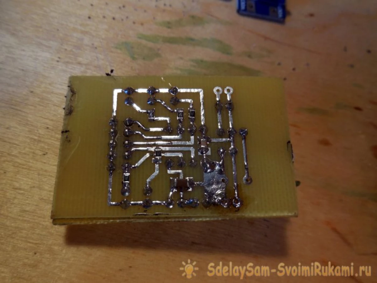
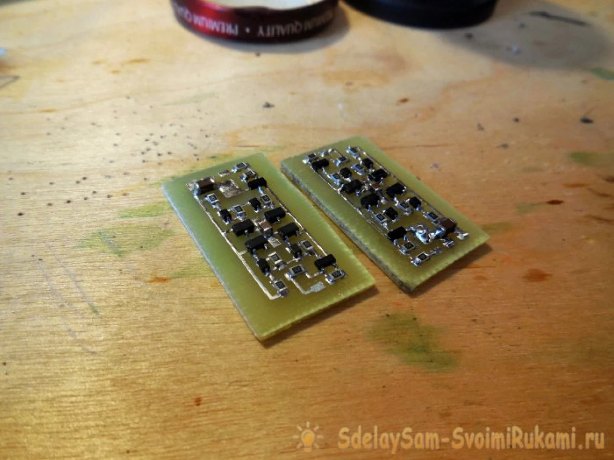
The engine is connected to this scheme, and it contains two inputs - In1 and In2, 3-5 volts were submitted to one input - the engine rotates in one direction, 3-5 volts were submitted to another - the motor rotates in the other side. If the voltage is not served any input, or is supplied to both inputs immediately - the motor does not rotate, this is such a simple logic of the work. The diagram has 4 field transistors that will switch the motor, so they must be calculated on a sufficiently large current. Two of them are N-channel, you can use AO3400, other two P-channels, suitable AO3401. Also on the diagram there are two bipolar NPN transistors, BC847 is suitable or any other similar. In order not to take a lot of space on the chassis, I recommend to assemble this scheme on SMD components. Diodes are any like, for example, 1N4148W. On the power input of this scheme (designated as 12 V), the voltage from the converter is supplied. Please note that the scheme needs to be collected in two copies - for the left and right motor, they will be powered accordingly from one and from the second converter. Photos of the collected circuit boards below.
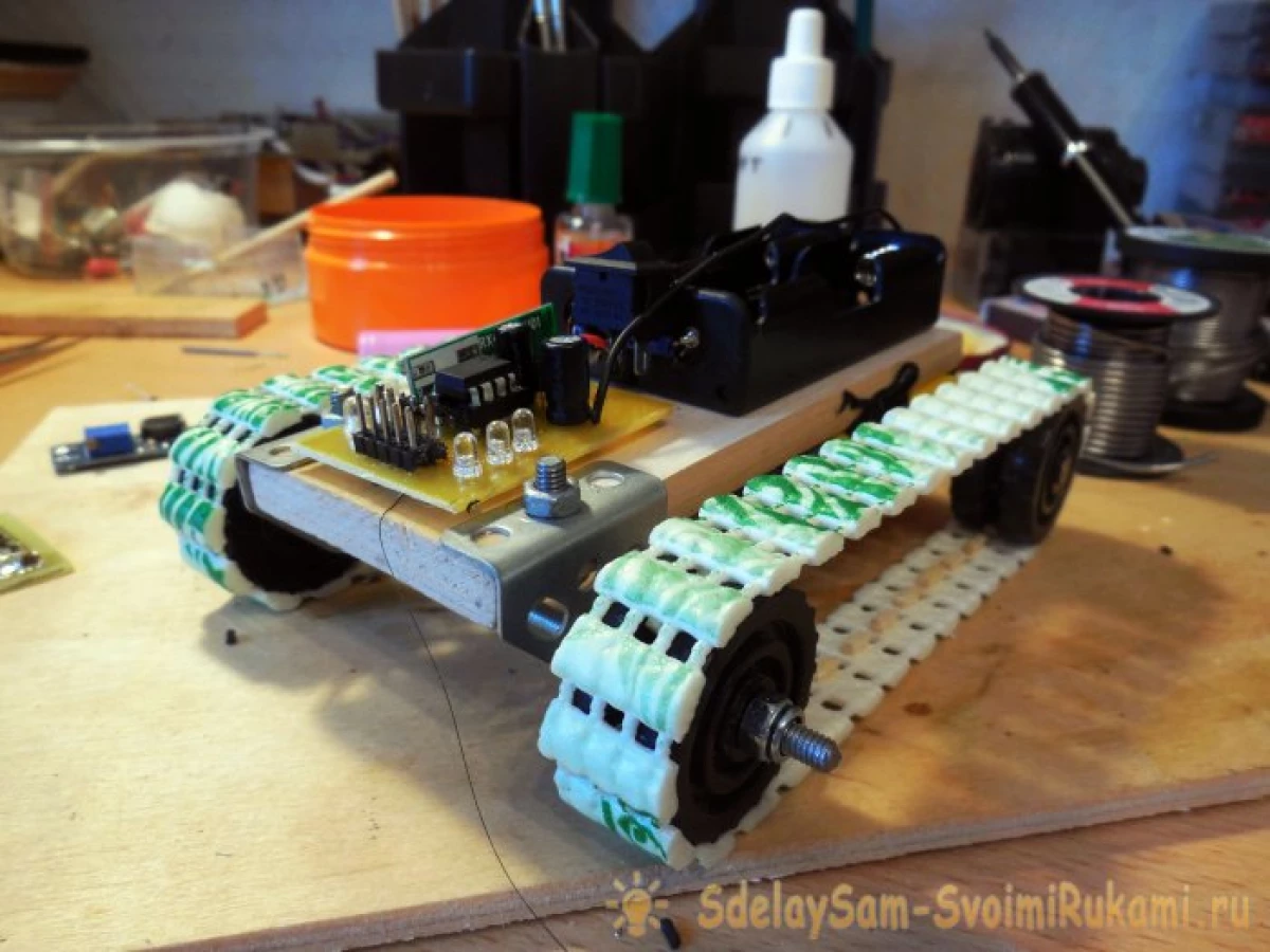
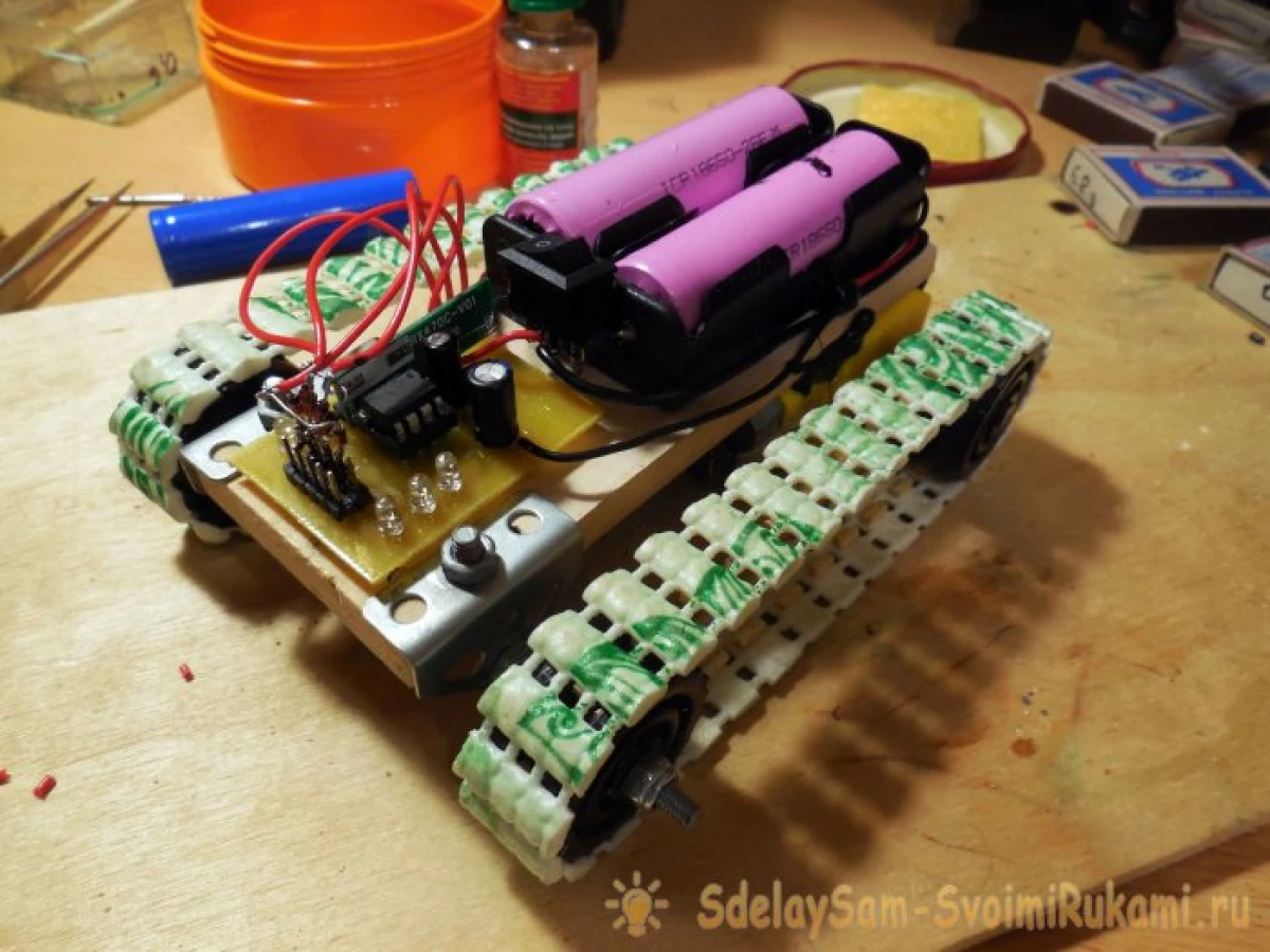
Now you can proceed directly to the installation - and first of all it is worth installing a couple of holding on the top of the chassis for 18650 batteries, all the electronics will be powered, the batteries are connected in parallel.
Before the batteries, in front of the decoder, the decoder board is installed, you can immediately connect it through the switch to the Holders Contacts. For convenience, 5 LEDs are installed on this board - the corresponding LEDs will light up when the remote key is pressed.
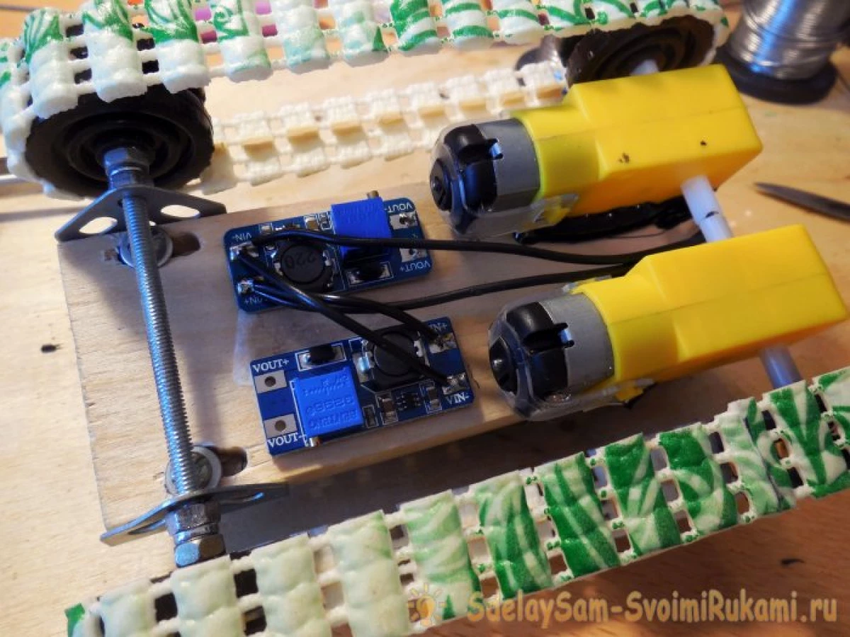
On the lower part, under the chassis, a pair of converters and a pair of platpheres are attached. Immediately, everything is connected by wires - the inputs of the converters through the switch to the holders, the outputs of the converter to feed the boards of the bridges, and the outputs of the bridges, in turn, already to the motor. It should be borne in mind that the motors under load can consume quite high current, respectively, at the input of the converters, the current consumed will be about 2 times more and some points can reach 1-1.5 amps, so it is necessary to supply power sufficiently thick wires.
The last, the final assembly stage remains - you need to connect the outputs of the decoder (4 outputs of 5) to the inputs of bridges (IN1, IN2) will be activated, so that when you press the device, the machine reacted in the desired manner. Namely:
- Pressing the "forward" - both engines rotate in one direction.
- Pressing "Back" - both engines rotate in the opposite direction.
- Pressing the "right" - the left motor rotates forward, right back, the machine takes place on the spot clockwise.
- Pressing the "left" - the right motor rotates back, left forward, the machine unfolds counterclockwise.
- The simultaneous pressing of "forward" and "right" - the left motor rotates forward, the right thing stands on the spot, thus, a smooth turn occurs.
- Simultaneous pressing "forward" and "left" - similarly, but in the other way.
To implement such logic, you need to connect the outputs of the decoder to bridge inputs in such a way as shown below.
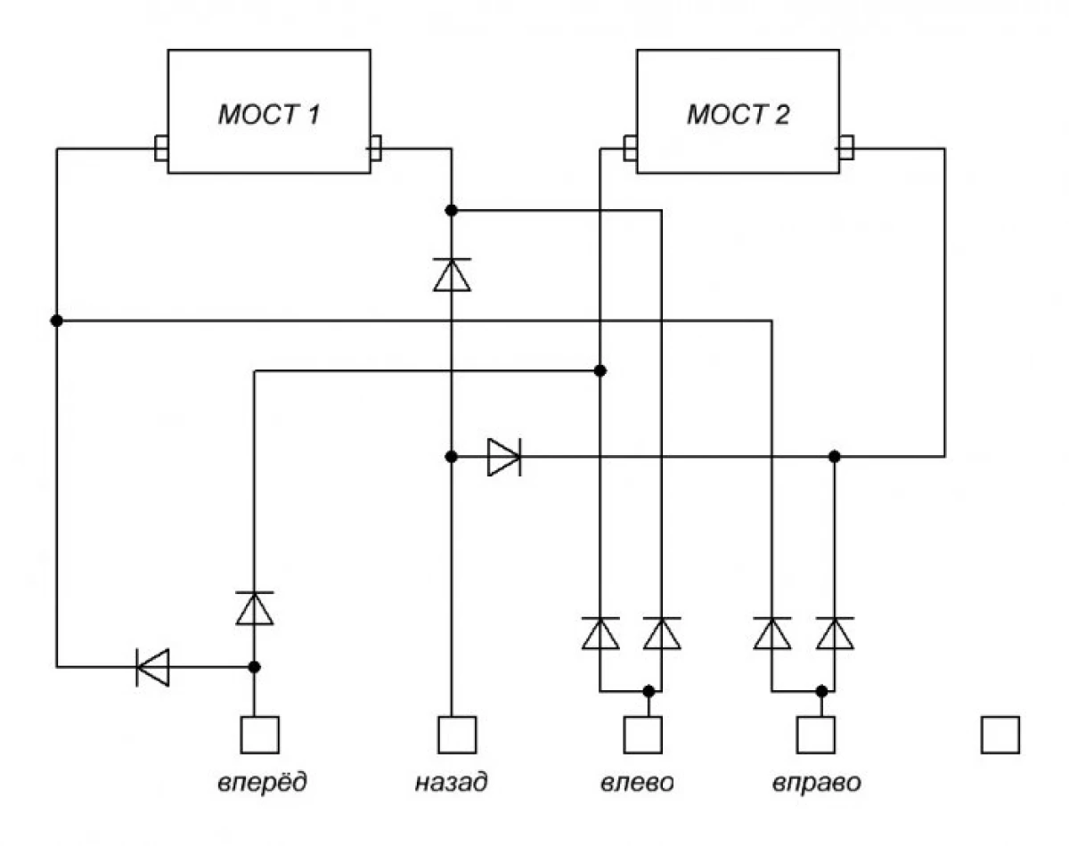
The bottom of the decoder is shown below, while one of them is free, it can be used for other actions. Diodes Here you can use the same 1N4148, soldered them by mounting right on the outputs of the decoder.
Test
This is completed on this machine, you can insert batteries and check the operation. At the same time, it will not be superfluous to check the consumption current - in the absence of teams from the console, it should be small, about several tens of mA. The distance of the console will depend on the used receiving modules and the transmitter - most often they provide a zone of confident reception about 20-30 meters in urban conditions, which is quite enough to control the machine. It will help to significantly increase the range of the antennas, you can take pieces of copper wire with a length of 17 cm (for frequency of 433 MHz) and solder to modules to "Ant" contacts.
Thus, it turned out a very busy toy for children and adults - PVC-rug caterpillars provide excellent clutch with any surfaces, so the machine easily overcomes obstacles. The advantages of the caterpillar option can also be attributed to the simplicity of control - it is not necessary to install additional steering mechanisms, all the control occurs only due to the change of the direction of rotation of the tracks. The lack of described design chassis can be called a small "road clearance" - the motors are located under the bottom and occupy there quite a lot of space, however, it does not interfere with the pleasure of driving, and if desired, this lack can be eliminated by adding an additional axis for Rear wheels and placing motors from above. Successful assembly!