
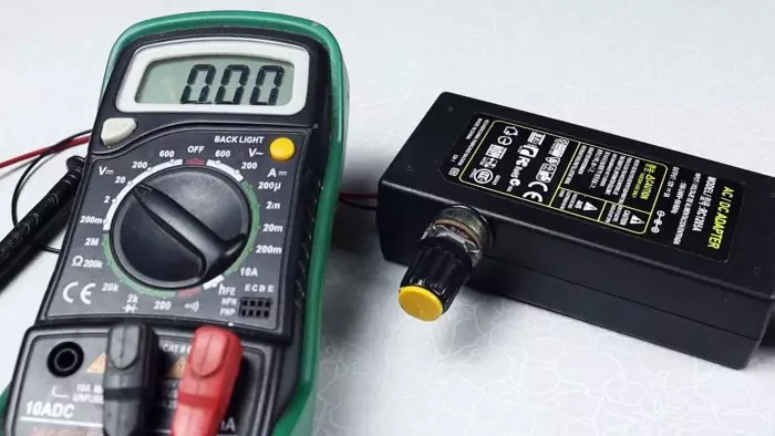
This instruction will help you to remake the power supply to the adjustable 3-25 V. If you have a power supply from a laptop by 19 V or a block from LED garlands by 12 V, then all such sources can be turned into adjustable, and set any voltage to the output rotation of the variable resistor.
Need
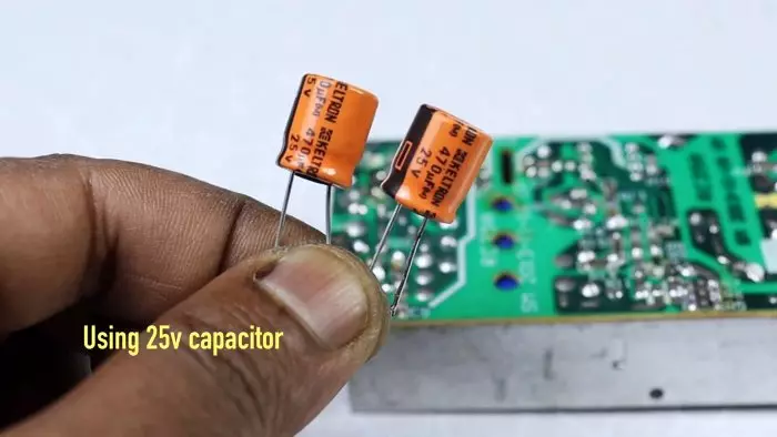
- Two condensers 470 μF 25 V.
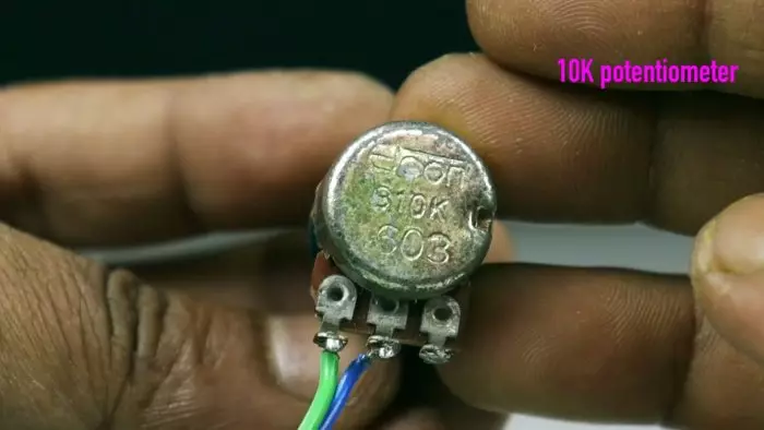
- Variable resistor 10 com.
- Resistor 2.2 com.
Alteration of the power supply unit with a fixed voltage into a source with adjustable voltage

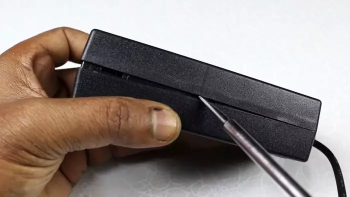
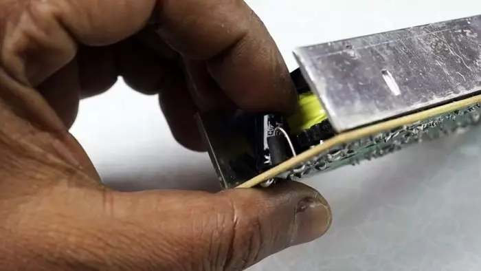
Open the block body with a screwdriver. Of course, not all the housings have latches, if it is glued, then how to disassemble it here -
It appears the entire fee of the pulse power supply.
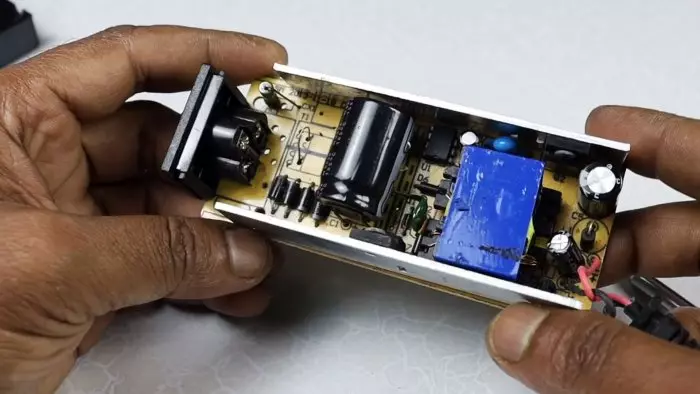
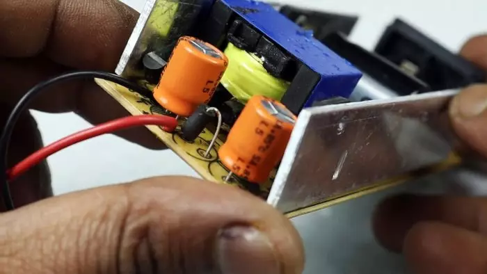
All that the left of the blue transformer we will not touch. This is a high-voltage part and she does not interest us. On the right, the low-voltage part consists of several elements, here it will be refined.
Schemes and theory of refinement
The unit has stabilization by feedback through the optocoupler. This optrone controls the TL431 stabilizer microcircuit. It has 3 outputs and looks like a transistor.
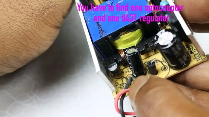
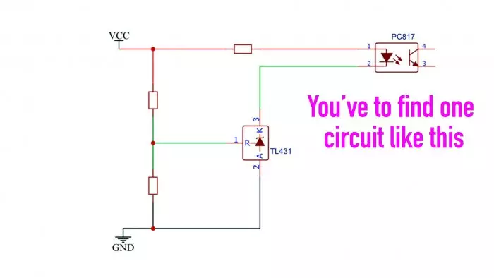
(If you do not have a chip TL431 in the block, then it is possible that stabilization is achieved by the use of Stabitron. How to modify such a block Read here -
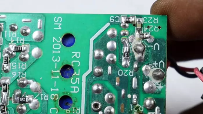
) One resistor in the optics chain restricting, other two dividers at the output of the chip. Behind the board, these resistors are clearly visible.
That is, if you change the fission factor at the input of the chip, then the output voltage on the output of the power supply will be changed and the output voltage will be changed. This is necessary to replace one resistor, and instead of another to connect an alternating. Approximately like this:
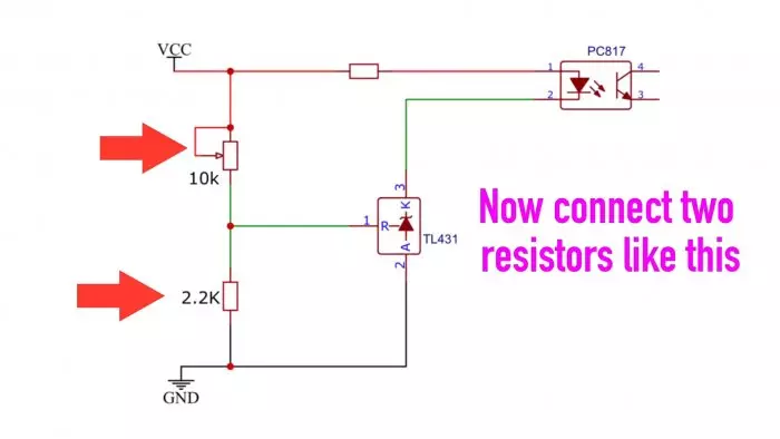
We drop the divisor resistors.
Be sure to replace the output capacitors to other with a higher operating voltage.
Also drop them.
Separate new ones.
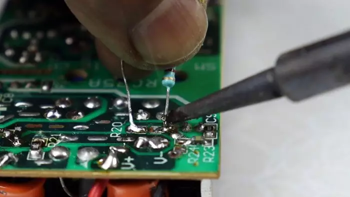
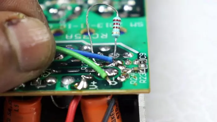
We solder the resistor 2.2 com, according to the process of refinement.
We take a variable resistor, solder the wires to it.
We solder the wires to the board instead of the chip of the resistor.
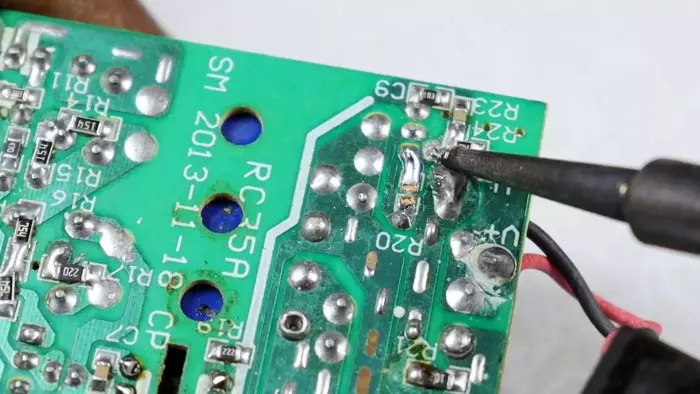
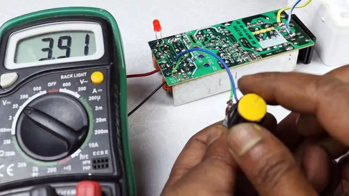
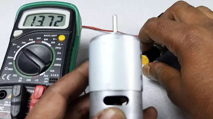
Now, very carefully, we turn on the unit into the network and check the work. Connect the multimeter to the output.
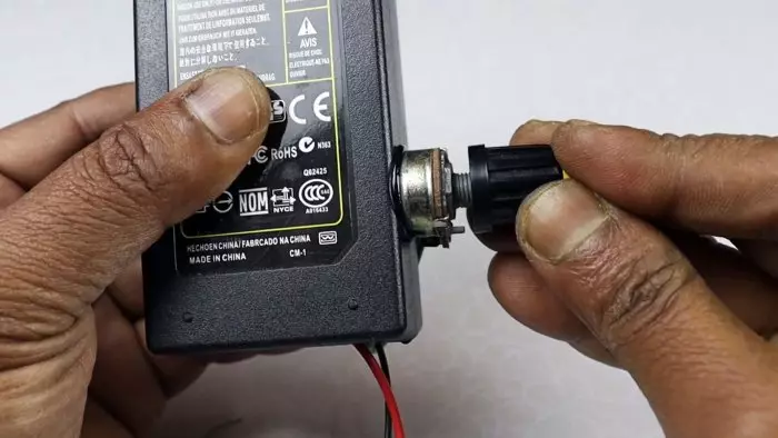
If everything works properly, then we collect the case. Since there is no additional place in the case, we will bring a resistor outside by gluing it with a side of glue.
Check under load. The source is well regulated and outputs the voltage in the range of 3.4-21.5 V.
Everything works fine.
A few words about safety technician
- Before disassembling the block, if you only disconnected it from the network, be sure to wait a few minutes until all internal containers are discharged.
- The output voltage, with the maximum position of the variable resistor, should not exceed 25 V, as the output capacitors may fail. To reduce adjustable voltage, increase the resistance of the resistor 2.2 com.